Off My Rocker
I am in the final stages of reassembling my 1953 Square 4 MK II engine. This has been a long, painful, expensive episode of more than 2 years after a rod failed during a short ride.
I have been fortunate during this period to become acquainted with a guy I now believe to be the foremost expert (and craftsman) of these engines (as well as most other vintage British marques), Paul Ackerman, whose shop is in the village of Tenants Harbor, Maine.
Paul has guided me through the rebuild process with unbelievable knowledge on every imaginable aspect of this deceptively complex engine.
The final piece of the puzzle involved addressing issues with the rocker shafts. These shafts are drilled from one end at the factory for oil passage. The factory then plugged the drilled end of the shaft with a threaded aluminum plug. Paul insisted (correctly it turned out) that these plugs had to be removed and the internal passageway cleaned of the 75 years of gunk accumulation. The problem is.. at the factory, for unknown reasons, the aluminum plugs were filed flat on the ends, so that there is no slot for screwdriver removal. The only solution, according to Paul, is to carefully drill the center of that plug, then gently remove the remainder with an easy-out.. right! Not as easy as it seems. I elected to turn this process over to him.

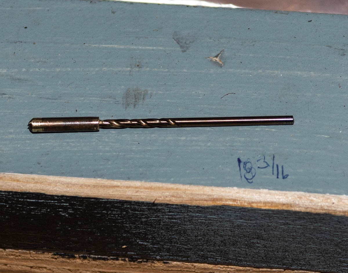
Rocker Shaft threaded plugs.. center drilled and removed with a screw extractor
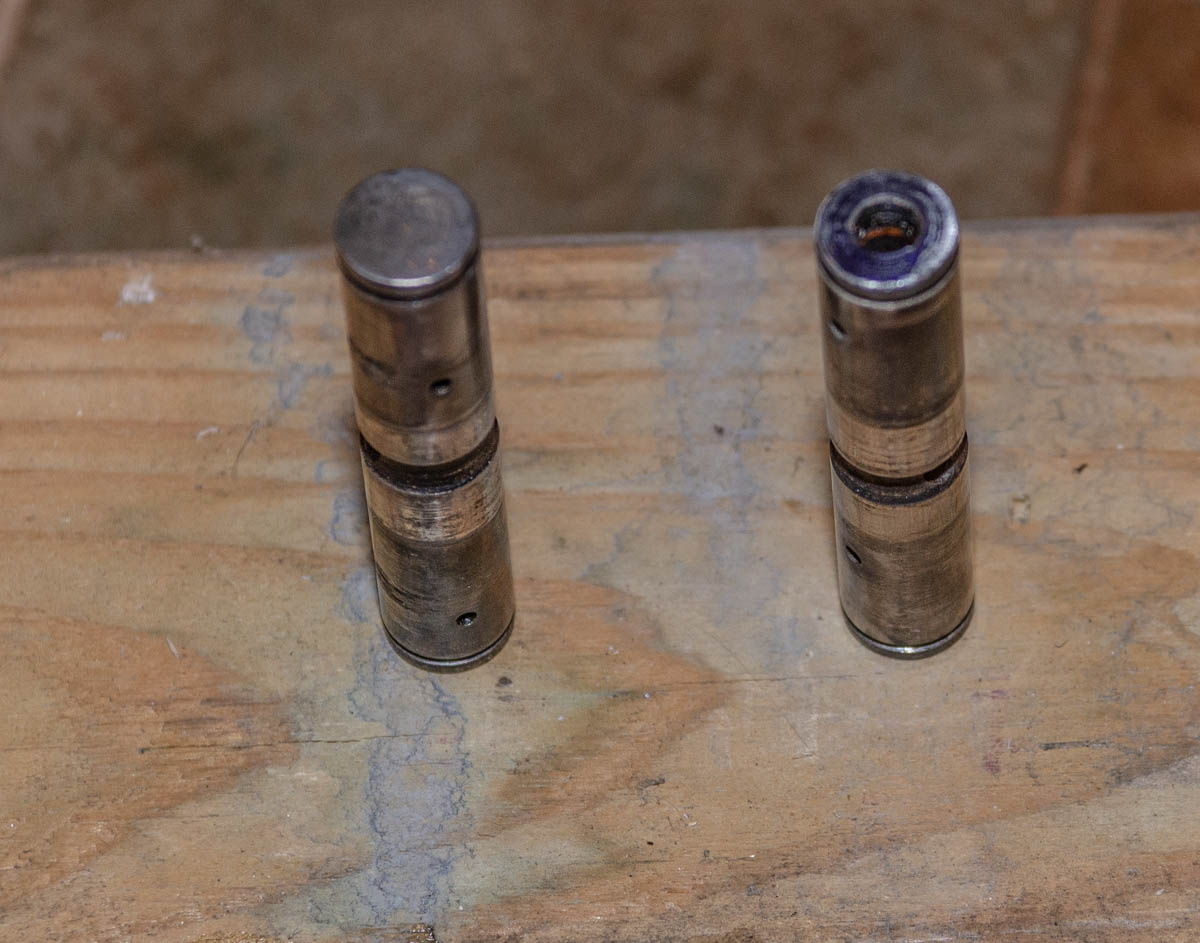
Rocker Shafts showing the solid end, and the “plugged” end, with threaded plug removed
I am pleased to say that we left the slot intact when installing the new plugs, so that some owner in the future will not have to deal with this same issue.
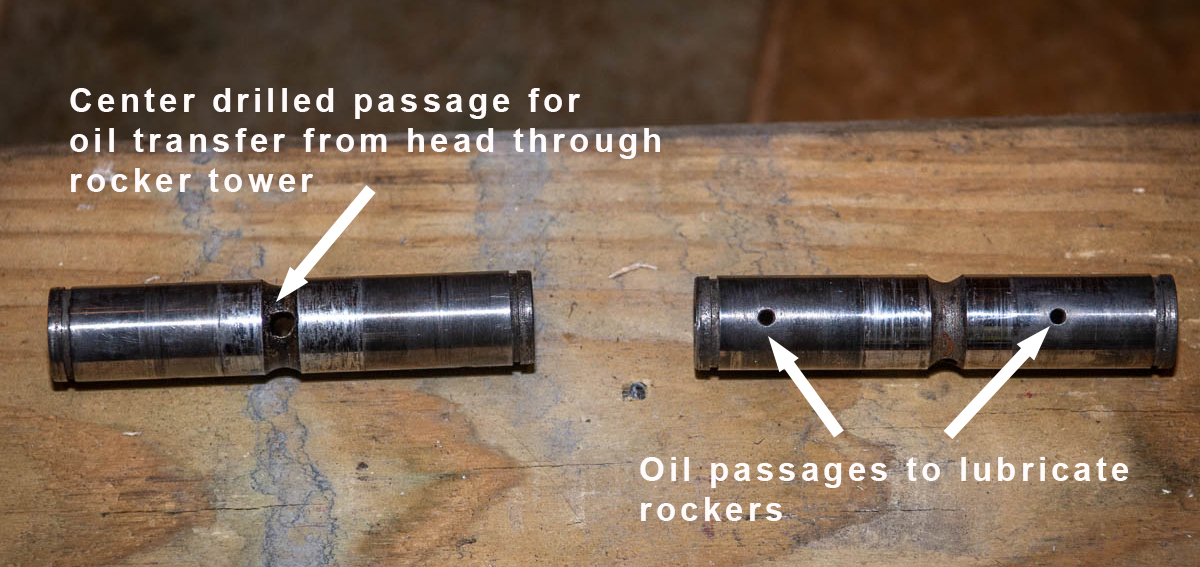
The next issue we encountered dealt with the fitment of the shaft into the rocker tower. The oil passage through the rocker block feeds through a hole in the center of the rocker shaft. This hole must absolutely be lined up with the passageway in the rocker tower to allow oil to flow into the hollow shaft from the head below to lubricate the rockers themselves, and to provide passage of oil from one rocker tower to its partner, since there is only ONE oil passage per side from the head to one of the two rocker towers. The other companion rocker relies on the external oil feed pipe to get its oil supply:
Since it is critical that the oil passage drilling in the center of the rocker shaft be lined up with the corresponding upper and lower passages on the rocker tower, obviously the shaft cannot be allowed to rotate. This is accomplished at the factory by manufacturing the shafts dimensionally for a press fit. Unfortunately, over time, the shaft CAN become looser and rotate, creating a partial or full blockage of oil supply to the rockers. This is what we discovered with my engine, with at least one shaft having rotated over the years to almost fully block the oil supply.
The solution? Either source new rocker blocks and shafts, or chrome plate the shaft, then turn it down for the proper interference fit. Paul was able to source NOS rocker towers from Draganfly in the UK, along with companion shafts for the two original ones he found to be unacceptably loose.
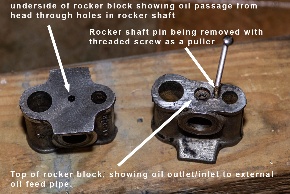
Removing the rocker shaft is yet another major hurdle. The shaft is held laterally in place (but not rotationally) via a machined groove in the center of the shaft (see previous photo), and a brass pin through a drilled hole which intersects the groove in the shaft to prevent sideways movement. Unfortunately, the drilled passage for that pin does NOT go all the way through the rocker tower, so it can’t be just driven out as one would expect (another marvel of British engineering). Instead, the only way to remove these pins is to carefully drill through the center, then tap threads for a #6 screw and use that screw to pull out the pin (see photo above and below)
Brass pin center drilled for removal
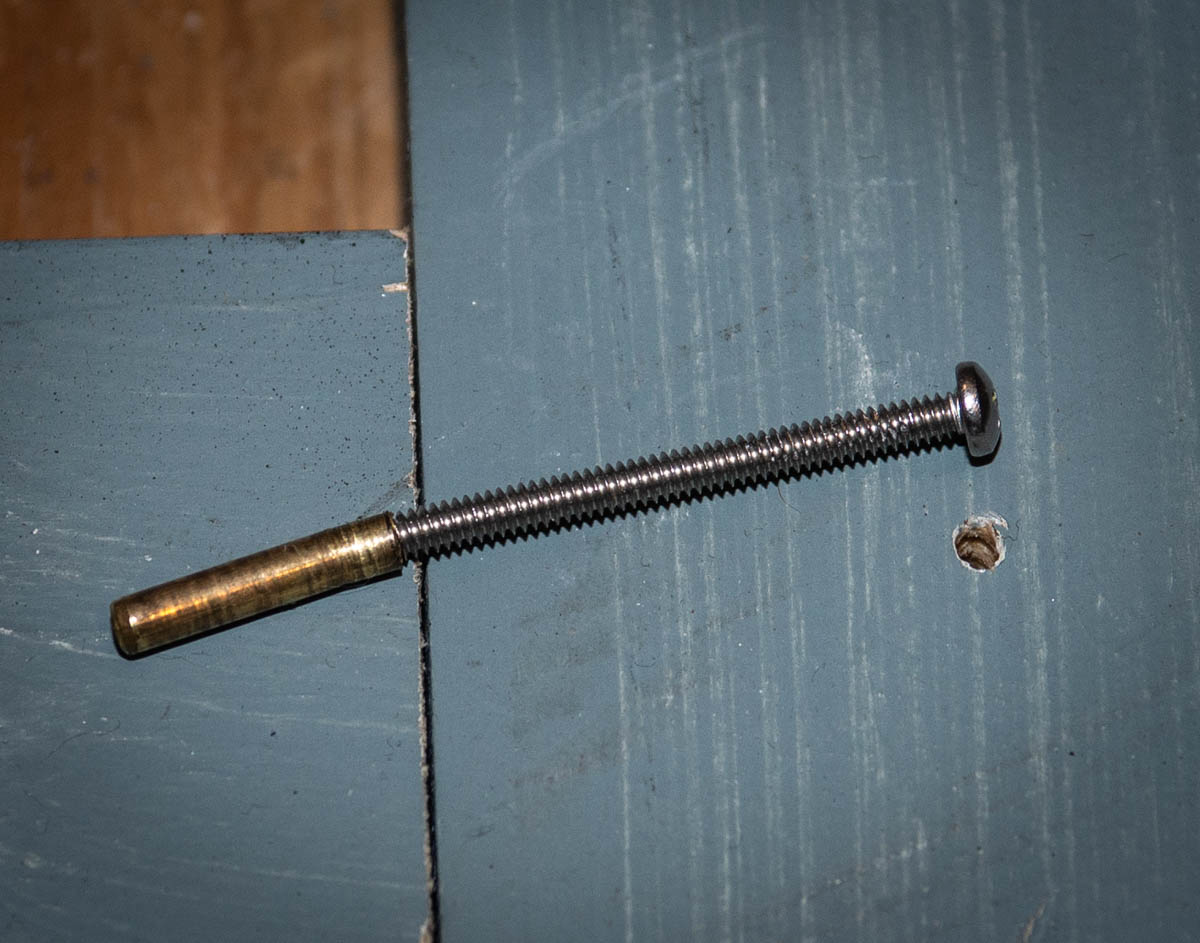
Pin is tapped for #4 screw, then the screw used to extract the pin
After installation of each of the rocker assemblies to the head, it is necessary to check clearance between pairs of side-by-side rocker arms. According to Paul, it is not unusual to have actual physical contact between two rockers at the pushrod end. If this is the case, then the circlip holding the rocker to the shaft must be removed, followed by the rocker arm, and the side of the casting reduced using, preferably, a belt sander, to provide adequate clearance:
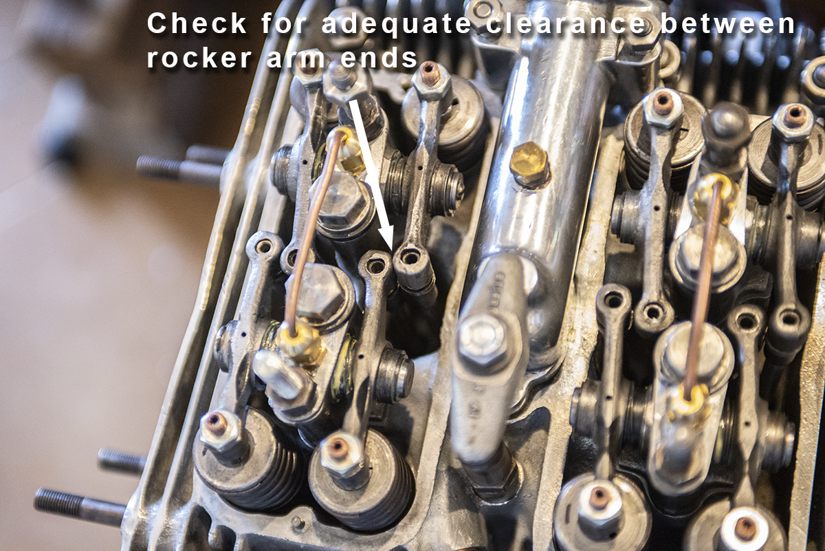
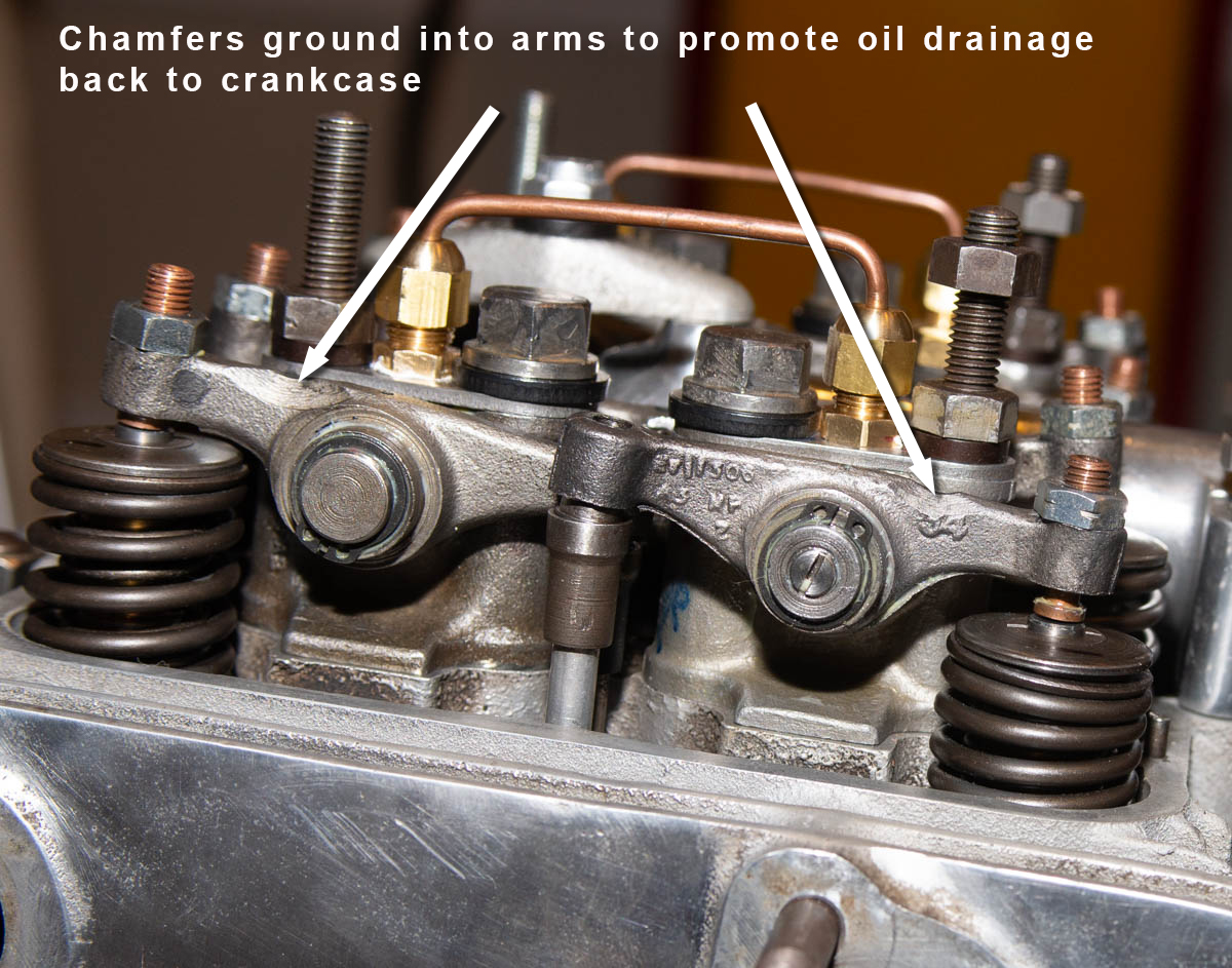
One enhancement to the rocker train that Paul supplies is an improved rocker-to-rocker external oil line kit. This kit consists of threaded flare fittings and copper line for each of the pairs of rockers. It requires drilling and tapping the rocker towers, using the existing oil passage holes as guides. The advantage of this system is that the cross pipe can be easily and quickly removed for re-torquing the 4 center head sleeve nuts underneath the pipe.
In the same photo below, you can also see the improved valve clearance adjustment hardware that Paul also supplies.. the adjuster screw has an internal hex head, so an allen wrench can be used to turn the screw during adjustment, replacing the square male head on the original adjusters.
Finally, in the photo below, you can see the chamfers that have been ground into the adjuster side of each rocker arm, per the Waller manual, purportedly to reduce oil flow down the valve stem and past the valve guide.